TECHNICAL KNOWLEDGE BASE
KB Series
KB Series
Specifications
KB-3SD Technical Specifications

Audio-Only Sub-Master Station for the KB Series. Line Drawing Specifications Power Source 22V DC supplied from Master Station Current Consumption 85mA (max.) 50mA (standby) Communication Handset simultaneous communication Wiring 2-conductor, PE insulation, Aiphone wire #871802 when not using Central exchange unit Wiring Distance Master Station to farthest Sub Master Station: 165′(22 AWG) 330′(18 AWG) Mounting Surface […]
RY-1824L Technical Specifications
Line Drawing Specifications Features Normally open (N/O) contact with a high current rating for door strikes Normally closed (N/C) contact with high current for magnetic locks Use with any 18-24V system that requires door release Power Source Supplied by Master Station or CEU Contact Rating 250V AC, 8A 30V DC, 5A Compatible Stations Form […]
RY-ES Technical Specifications
Line Drawing Specifications Features Allows an external device to be triggered when the intercom is called External device will be activated when the door station calls in Power Source 12-24V DC, 12-16V AC – supplied by Master Station Contact Rating 125V AC, 1.0A 30V DC, 1.0A Compatible Stations External Signaling Relay for AX Series, […]
IER-2 Technical Specifications
Line Drawing Specifications Features Announces chime tone only Adjustable volume (3 positions) Indoor mounting Compatible Stations Call Extension Speaker for DB Series, JF Series, JK Series, JO Series, JP Series, KB Series, or NIM Series Mounting Surface mount directly to the wall or 1-gang box Dimensions 4-3/4″H x 3-1/2″W x 1-1/8″D Weight 0.33lbs (150g)
MCW-S/B Technical Specifications
Line Drawing Specifications Features Allows desk mounting of master and / or handset station Mounting hardware included Station is propped up for easier viewing Pre-drilled mounting holes Constructed with sturdy ABS plastic Adjustable to 45° or 60° angles Compatible Stations AX-8M, AX-8MV, AX-8MV-W, DB-1MD, DB-1SD, GT-1A, GT-1C7, GT-1M3, GT-2C, GT-2H, JF-2HD, JF-2MED, JK-1HD, JK-1MED, […]
SBX-ACE Technical Specifications
Line Drawing Specifications Features Weather resistant Includes space inside for wiring Mounts to 1-gang box or ring Can mount directly to wall surface Material 18 gauge polished stainless steel Mounting Surface mount directly to the wall or 1-gang box Overall Dimensions 7-1⁄16″ H x 9-⅛” W x 4-¼” D (top) 1-⅝” D (bottom) Faceplate […]
KMB-45 Technical Specifications
Line Drawing Specifications Features 45˚ Mullion Mounting Bracket for C-D, GT-D, IF-DA, JO-DA, JP-DA, KB-DAR, KB-DAR-M, or LE-D Can mount to either right or left of the door Mounting Surface mount directly to the wall or mullion Dimensions 5-1/2” H x 5-1/2” W
KAW-D Technical Specifications
Line Drawing Specifications Features Provides a better viewing angle for the camera Compatible with Aiphone 1-gang surface mount door stations Angles 1-gang door stations outward by 30° Can mount to either right or left of door Hinged cover for mounting door station Material ABS Plastic Mounting Surface mount directly to the wall or 1-gang box […]
AC-10S Technical Specifications (Discontinued)
Line Drawing Specifications Power Source 12-24V AC or DC Current Consumption AC: 100mA (max.) DC: 70mA (max.) Number of Relays 2 Relay Contact Capacity 24V DC, 3A (resistive load) 1A (inductive load) 24V AC, 3A (resistive load) 1A (inductive load) Mounting Surface wall mount Protection Rating IP54 Operating Temperature -4°~140° F (-20° ~ 40° […]
MAW-B Technical Specifications
Line Drawing Specifications Power Source 24V DC Supplied from Master Station Current Consumption 2.5W (max.) 0.5W (standby) Wiring Distance Up to 26′ with 22AWG wire Contact Rating Dry closure contact for general lighting of less than 100W Mounting Surface wall mount Operating Temperature 14°~104° F (0° ~ 40° C) Dimensions 2-7⁄16″ W x 4-1⁄8″ H […]
KB-3MRD Technical Specifications
Line Drawing Specifications Power Source 24V DC (Supplied by PS-2420UL for every two sub master stations) Power Consumption 710mA Maximum, 230mA Standby Communication Handset Screen 4″ TFT color LCD Door Release Contact 24V AC/DC, 1A (Normally open contact closure) Mounting Surface wall mount Electrical Box 2-gang box Operating Temperature 32° ~ 104°F (0° ~ 40°C) […]
IE-SSR Technical Specifications
Vandal Resistant Sub Station for the AX, IE, and KB Series Systems. Line Drawing Specifications Power Source Supplied from Central exchange unit or Master Station Communication Open voice hands-free communication Wiring Door Station to Central Exchange Unit: Cat-5e or 2-conductor, PE insulation, Aiphone wire #822202 when not using Central exchange unit Wiring Distance 980′(Cat-5e with […]
IE-SS/A Technical Specifications
Line Drawing Specifications Power Source Supplied from Central exchange unit or Master Station Communication Open voice hands-free communication Wiring Door Station to Central Exchange Unit: Cat-5e or 2-conductor, PE insulation, Aiphone wire #822202 when not using Central exchange unit Wiring Distance 980′(Cat-5e with AX Series) 1,180′(18′ AWG) 500′(22 AWG) Faceplate Material 12-gauge stainless steel Mounting […]
IE-JA Technical Specifications
Flush Mount Door Station with Stainless Steel Cover for AX, IE, and KB Series Systems. Line Drawing Specifications Power Source Supplied from Central exchange unit or Master Station Communication Open voice hands-free communication Wiring Door Station to Central Exchange Unit: Cat-5e or 2-conductor, PE insulation, Aiphone wire #871802 when not using Central exchange unit Wiring […]
IF-DA Technical Specifications
Surface Mount Door Station for the AX, IE, and KB Series Systems. Line Drawing Specifications Power Source Supplied from Central exchange unit or Master Station Communication Open voice hands-free communication Wiring Door Station to Central Exchange Unit: Cat-5e or 2-conductor, PE insulation, Aiphone wire #871802 when not using Central exchange unit Wiring Distance 980′(18 AWG […]
AX-DM Technical Specifications
Mullion Mount Door Station for the AX Series. Line Drawing Specifications Power Source Supplied from Central exchange unit Communication Open voice hands-free communication (auto voice actuation or PTT controlled by Master Station) Wiring Door Station to Central Exchange Unit: Cat-5e or 2-conductor, PE insulation, Aiphone wire #871802 when not using Central exchange unit Wiring Distance […]
KA-DGR Technical Specifications
Line Drawing Specifications Mounting Surface wall mount Material Stainless steel Weight Approx. 0.66lbs (300g) Additional Features Weather resistant for outdoor use Can be added to any existing KB-DAR or KB-DAR-M video door station
KB-DARM Technical Specifications
Line Drawing Specifications Power Source 22V DC supplied by KB Series Master Station Communication Hands-free Camera 1/4″ CCD Camera Angle 0~+40°(controlled by Tilt control pad on Master Station) Minimum Illumination 1 lux Wiring 2-conductor, PE insulation, Aiphone wire #871802 Wiring Distance 330′(22 AWG) 650′(18 AWG) Mounting Surface wall mount Electrical Box Single-gang box Operating Temperature […]
KB-DAR Technical Specifications
Line Drawing Specifications Power Source 22V DC supplied by KB Series Master Station Communication Hands-free Camera 1/4″ CCD Camera Angle 0~+40°(controlled by Tilt control pad on Master Station) Minimum Illumination 1 lux Wiring 2-conductor, PE insulation, Aiphone wire #871802 Wiring Distance 330′(22 AWG) 650′(18 AWG) Mounting Surface wall mount Electrical Box Single-gang box Operating Temperature […]
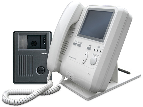
KB-3HRD Technical Specifications
Line Drawing Specifications Power Source 24V DC (Supplied by PS-2420UL for every two sub master stations) Power Consumption 260mA Maximum, 80mA Standby Communication Handset Screen 4″ TFT color LCD Mounting Surface wall mount or desk mount with MCW-S/A Electrical Box 2-gang box Operating Temperature 32° ~ 104°F (0° ~ 40°C) Dimensions 7-1/4” W x 7-3/4” […]
Wiring Diagrams
Wiring: KB Series Complete System

Wiring Diagram Wiring Distances KB Door Station to KB-3MRD: 330′ (22AWG) or 660′ (18AWG) KB-3MRD to farthest KB-3HRD/SD: 165′ (22AWG) or 330′ (18AWG) KB-3MRD to IF-DA: 450′ (22AWG) or 1,000′ (18AWG)
Common Issues
No Call Tone or Chime When A Door Station Calls KB-3MRD or KB-3HRD

Summary KB-3MRD or KB-3HRD, no chime or video from one or more door stations. Solution Check the DIP SWITCH SETTINGS underneath the handset, behind the buttons. Remove directory card. Switches 1, 2, 3 correspond to each door station. UP position is the OFF position, contrary to the labeling molded into the plastic. If these switches […]
Constant Call Tone on KB-3MRD
Summary Constant call tone, or odd buzzing on KB-3MRD master station. Solution Shorted wires on CN-12 can cause this issue to occur. Make sure unused wires on CN-12 are isolated (cut and insulate if necessary).
No Audio Through Handset While Using KB-3MRD/HRD
Summary No Audio through the handset due to improperly plugged-in connectors. Solution Make sure that all multi-pin connectors are plugged in securely and all the way. If the bottom connector is not fully plugged in, for example, audio will work through the base but not through the handset.
Transform Your Security Today
Connect with our local experts for product questions, demos, and assistance in designing your ideal security solution.
Contact Us
Recent Articles
Stay current with our latest technical resources. We update them regularly to support your evolving security needs.